Modules
Floor plans in Vision and in Field
CERQA has two separate floor-plan systems, one in Vision and one in Field. They are independent: a plan in one is not the plan in the other, and neither replaces or revises the other. This page covers both.
Two separate floor-plan systems
The two systems differ in where they live, what they are made from, and how they change. Nothing crosses between them.
| System | Where it lives | What it is made from | How it changes |
|---|---|---|---|
| Vision plan | The Vision tab | Generated from a point cloud | Regenerate from a new scan |
| Field plans | The Field tab | PDF sheets you upload | Replace Floor Plan, swapping one PDF for another |
A plan in one system is not the plan in the other
Generating a plan in Vision does not put a plan in Field, and uploading a PDF in Field does not change what Vision shows. Each tab keeps its own plan, and each has its own way of getting one.
Vision floor plans - generated from a point cloud
Vision takes a 3D point cloud as input, processes it into a 2D top-down representation, and lets you mark floor boundaries on the result. Vision generates the navigable plan from those boundaries, which is why the plan ties into Vision's 360 navigation natively: it comes from the same point cloud as the walkthrough.
This path needs a scan. If a 3D scan of the property is not available, there is no point cloud to generate a Vision plan from, and arranging the capture is the first step.
Step 1: Upload the point cloud
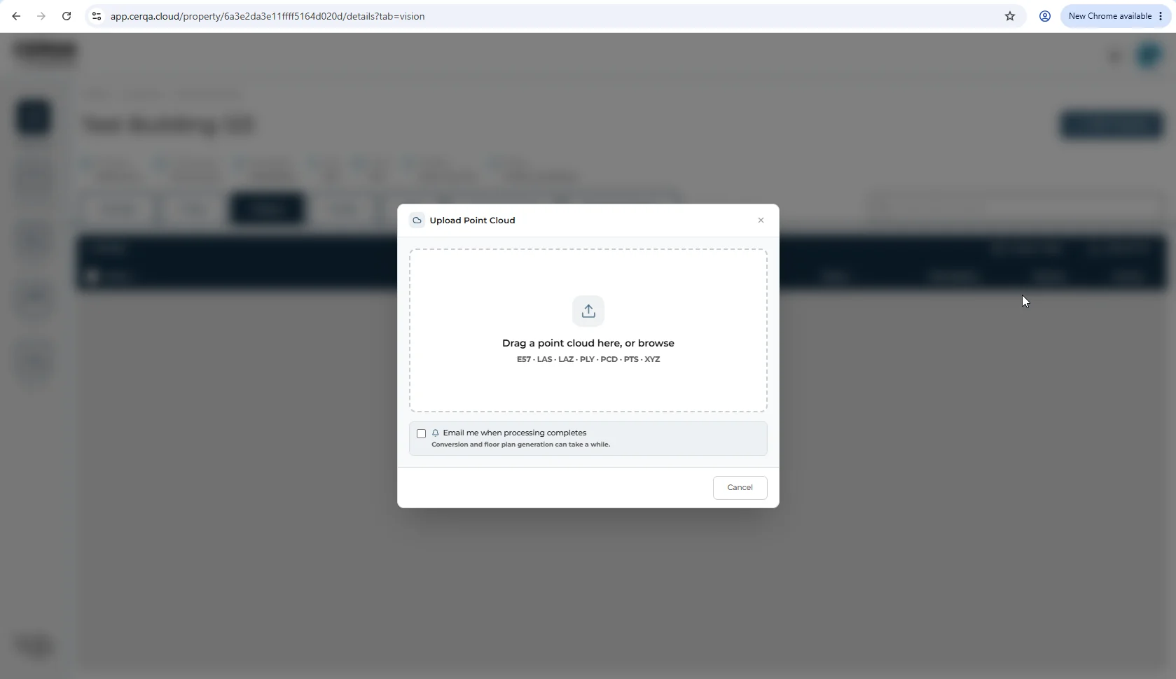
From the Vision tab on the property, open the Upload Point Cloud dialog. CERQA accepts common point-cloud formats (E57, LAS, LAZ, PLY, PCD, PTS, XYZ). Pick the file and start the upload.
Step 2: Wait for processing
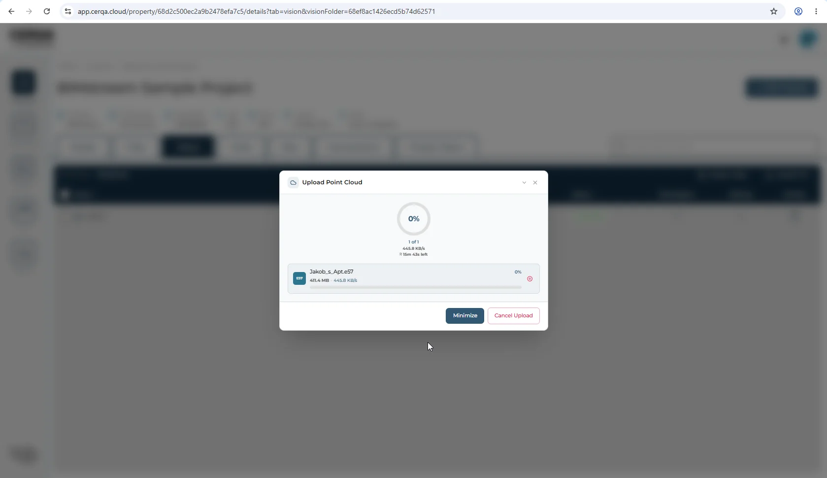
CERQA processes the uploaded point cloud (the conversion step takes the raw cloud and produces a derivative format optimized for viewing). The Vision sidebar shows the processing state and a progress indicator while the conversion runs; when it completes, the state moves to Ready and the floor-boundary step becomes available. CERQA can email you when processing finishes (optional; useful for large clouds that take longer).
Step 3: Define floor boundaries
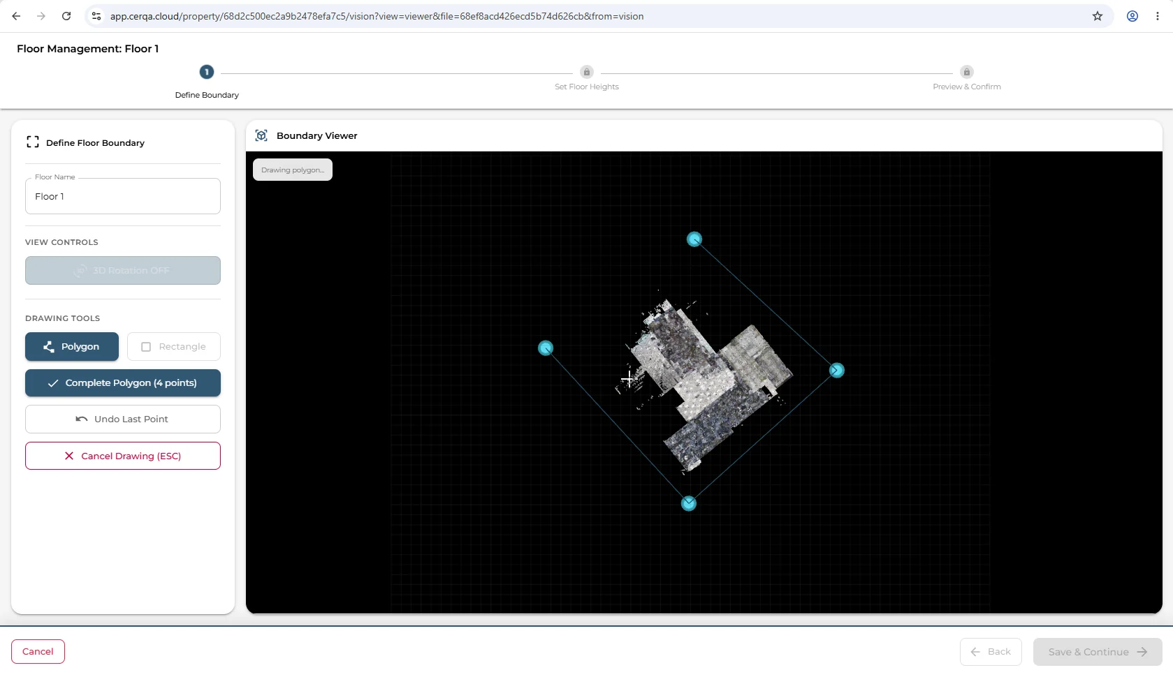
With processing complete, open the Define Floor Boundaries action. CERQA shows the top-down view of the processed cloud; you mark the outline of each floor on the property. For multi-floor properties, define one boundary per level.
Step 4: The generated plan is now live
Once boundaries are defined, CERQA generates the navigable floor plan and the property has a live plan on the Vision tab. From there you can walk through the 360 captures attached to the underlying point cloud.
A Vision-generated plan stays in Vision
The plan Vision generates is a Vision surface. It is not pushed to Field, so it is not the plan Field pins are dropped on. Field keeps its own floor plans, covered in the next section.
Field floor plans - PDF sheets you upload and replace
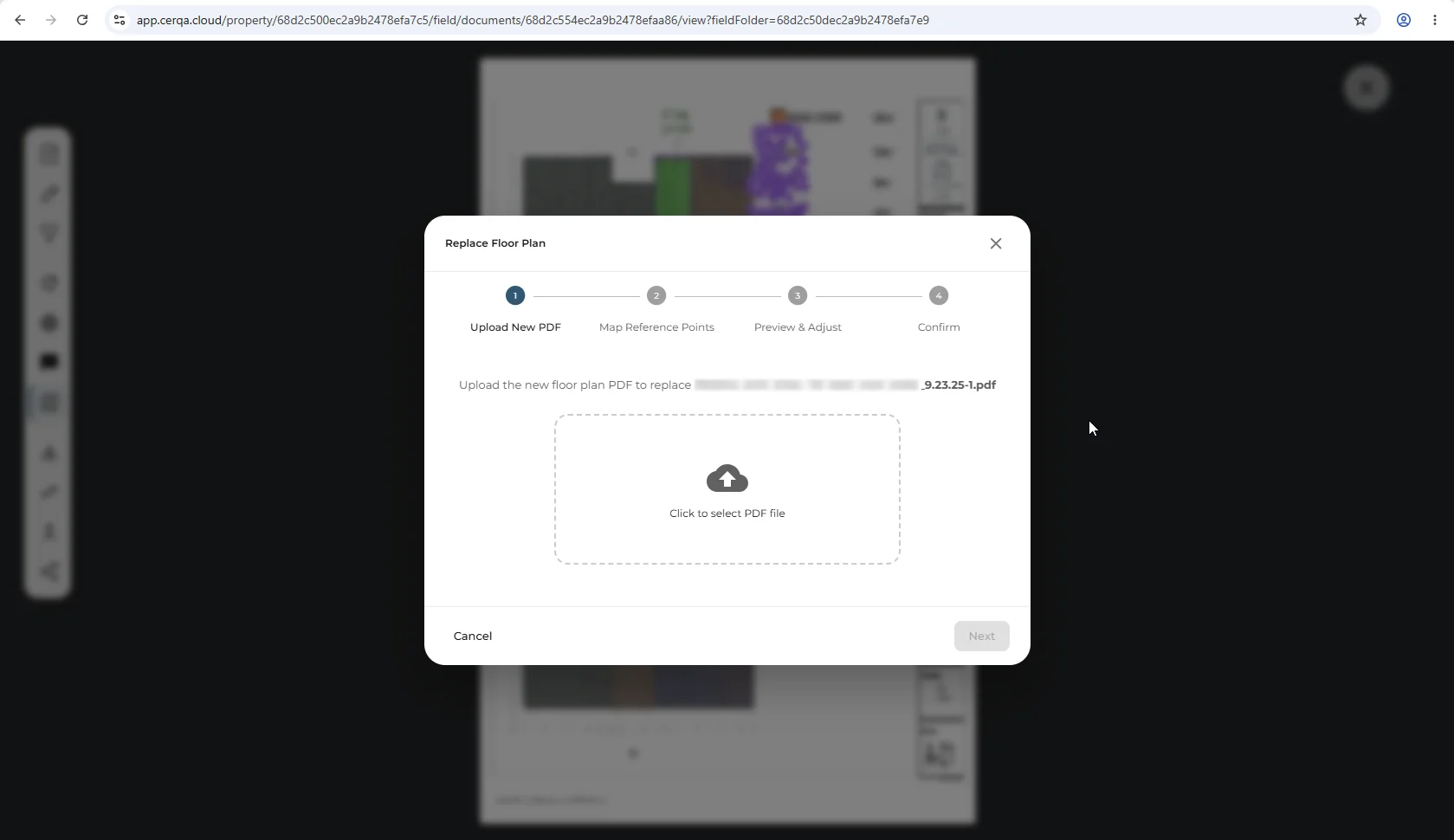
Field's plans are PDF sheets. You upload one, and when a revised sheet arrives you swap it in through the Replace Floor Plan wizard, which matches points on both PDFs so existing pins land correctly on the new one.
- 1Step 1: Upload New PDF - Open the Replace Floor Plan action on the Field tab and upload the new PDF version of the plan. PDF is the accepted input format here (not DWG, not PNG; if you have those formats, convert to PDF first).
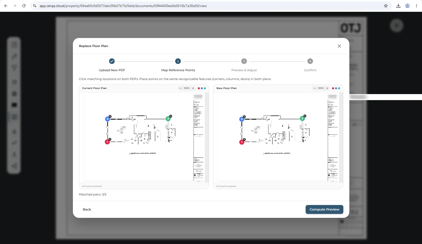
- 2Step 2: Map 2-3 Reference Points - CERQA shows the current plan and the new one side by side and asks you to click matching locations on both PDFs. Pick 2-3 shared landmarks (a corner, a column, a doorway) on each. These reference points anchor the coordinate alignment between the two plans, which is how CERQA knows where each existing pin should land on the new one.
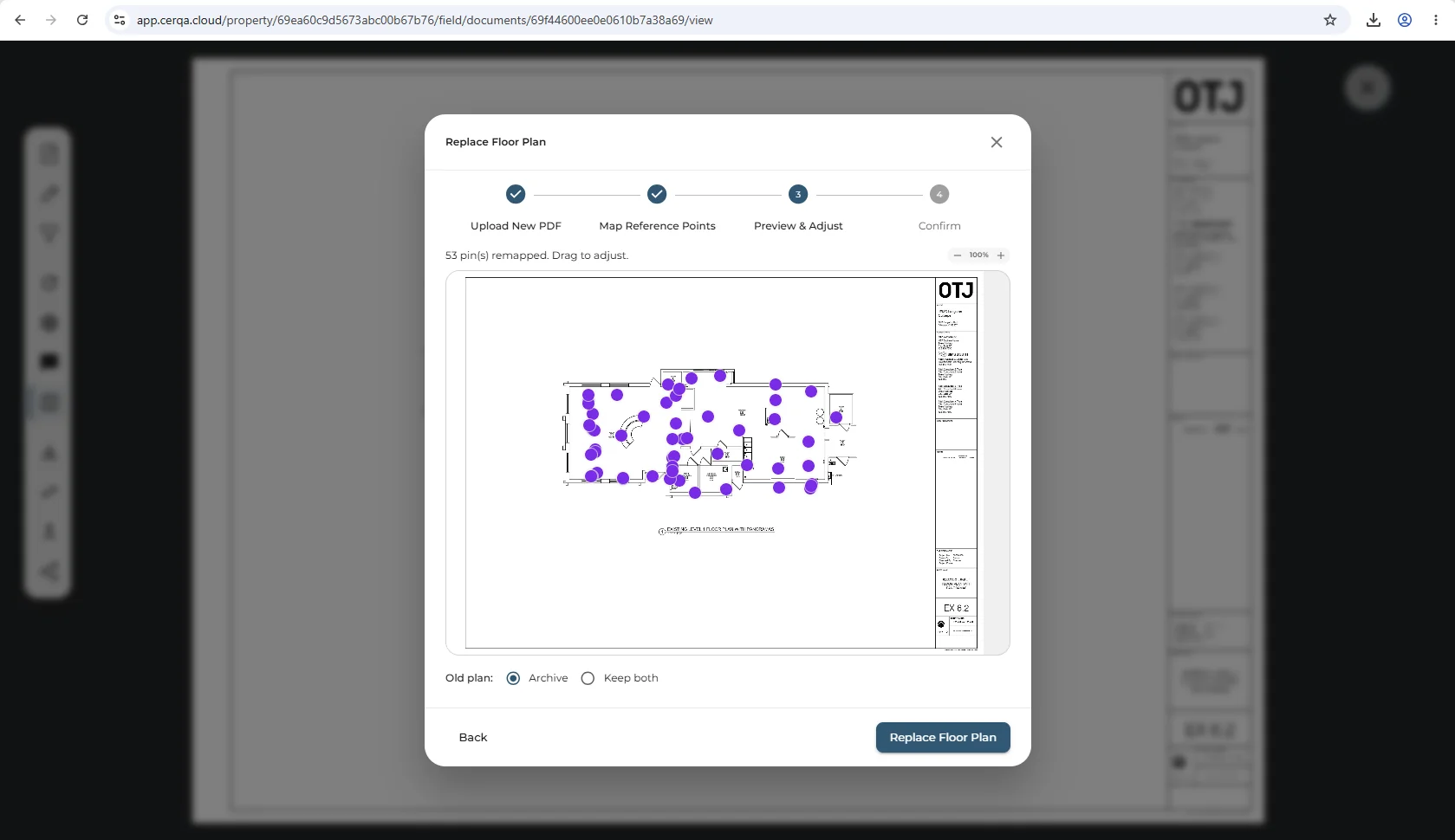
- 3Step 3: Preview & Adjust - CERQA shows the new plan with the existing pins overlaid in their remapped positions. Review the alignment; if any pins are visibly off, nudge them or revisit the reference points from Step 2. The preview lets you catch alignment issues before confirming.
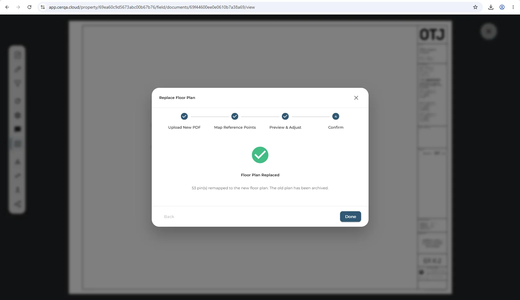
- 4Step 4: Confirm (optionally archive the old plan) - Confirm to commit the replacement. CERQA replaces the live plan with the new PDF; existing pins land on the new plan via the remap. An optional checkbox lets you archive the old plan rather than discarding it - useful for an audit trail of plan revisions.
What happens to pins on replace
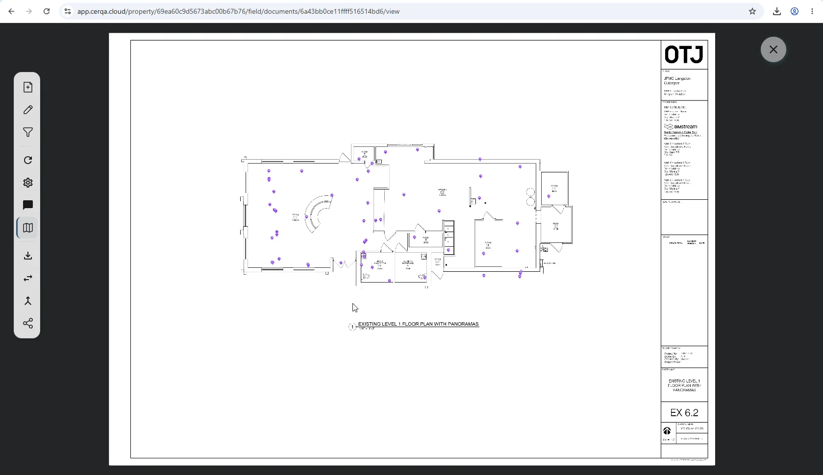
Existing pins are preserved. The reference-point remap moves them onto the new plan, so as long as the reference points are well chosen, pin positions land where they belong on the revised layout.
Deleting every plan on a property is not a self-serve action. For that, the path is your CERQA Account Manager via CA-14 - When to call your CERQA Account Manager.
Related pieces
- FL-01 - Field overview - the Field tab where its floor plan renders, where pins are dropped, and where the Replace Floor Plan action lives.
- VS-02 - Floor plans & navigation - the Vision floor plan view + the dual control system. VIEW MODE: Point Cloud is what backs the Vision plan on this page.
- F-04 - Roles and permissions - the complete role matrix for who can do what across CERQA. Generating or replacing a floor plan is available to Project Manager and above.
- CA-14 - When to call your CERQA Account Manager - the escalation path for deleting all plans on a property.