Modules
Floor plans & navigation
Vision opens on a property with the Immersive view as the default: a 360 panorama filling the work area, a floor plan mini-map in the bottom-right corner, the Vision sidebar down the left edge, and a level selector on the right for multi-floor properties. Two independent sidebar controls drive navigation: LAYOUT (how the floor plan and the 360 view share screen space) and VIEW MODE (which data layer is shown). They're separate. Any LAYOUT can show any VIEW MODE. This page covers what each control does, how they compose, and the mechanics (pin navigation, level switching) that sit alongside them. For the Vision overview (entering Vision, walkthrough pins, Capture image, Viewpoints), see VS-01 - Vision & 360 walkthroughs overview.
The default Immersive view
The default Vision opening on a property is the Immersive view: a 360 panorama fills the work area from one of the property's captures. Around it: the Vision sidebar down the left edge (with LAYOUT and VIEW MODE among its icons), a level selector on the right (e.g. Level 2 / Level 1 / Basement; this is where you switch between floors on multi-floor properties), and a floor plan mini-map in the bottom-right corner (with the current floor's pins visible at a glance). To reveal or expand the plan, use LAYOUT (Split View or Floor Plan); see below.
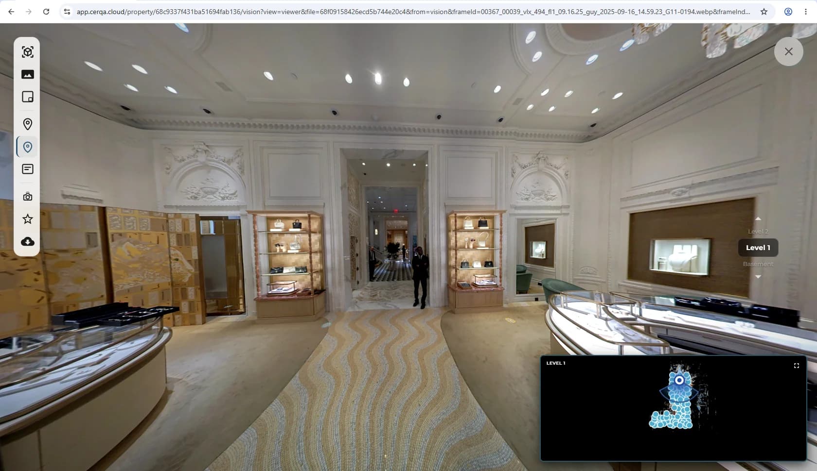
Two separate controls - LAYOUT and VIEW MODE
The dual-control system is the most-confused part of Vision navigation. They're two distinct sidebar icons, not one. Click either icon to open its flyout menu; each has its own three options, and the two compose freely.
- LAYOUT is how the floor plan and the 360 view share screen space: do you see only the plan, only the 360, or both side by side?
- VIEW MODE is which data layer is shown: the 360 photo panorama, the point cloud from the same capture, or the reconstructed 3D mesh.
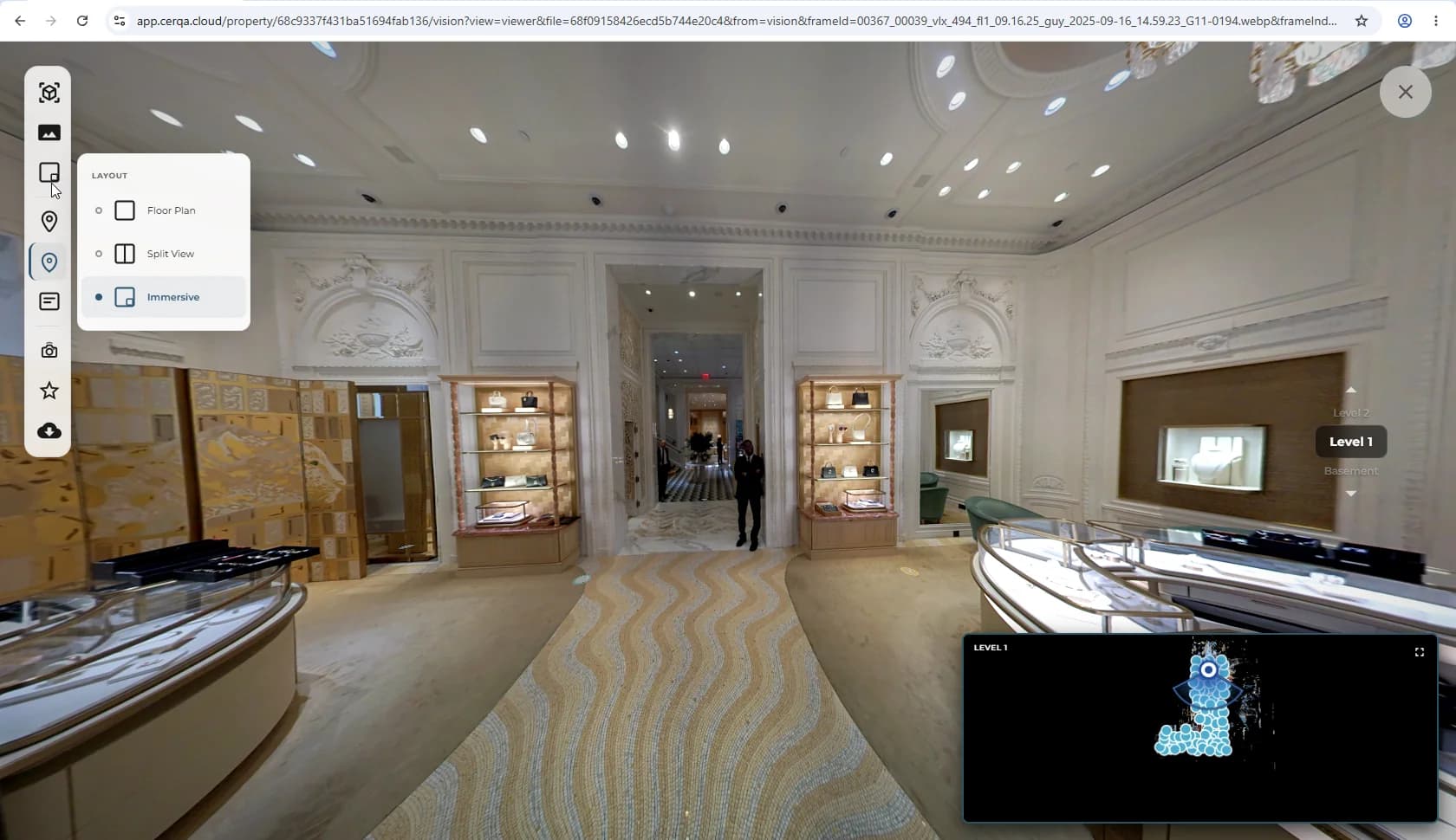
The two sidebar icons open their flyout menus independently (see the two figures below); the LAYOUT and VIEW MODE selections are stored separately, so switching one leaves the other alone.
Independent: any LAYOUT can show any VIEW MODE
Pick LAYOUT and VIEW MODE separately. Floor Plan layout with 360 view mode is one combination; Immersive layout with 3D Mesh view mode is another. Nine combinations are possible from the three options on each axis; all of them are valid.
LAYOUT options
Three LAYOUT options, picked from the LAYOUT control:
- 1Floor Plan - The floor plan fills the work area. The 360 view is hidden. Use this when you want to scan the property layout, find pins, or pick a starting point before entering a walkthrough.
- 2Split View - The floor plan and the 360 view share the work area side by side. Useful for keeping spatial context (where am I on the plan?) while you look around inside the 360.
- 3Immersive - The 360 view fills the work area. The floor plan is hidden. Use this for walking through the property without the plan in the way.
VIEW MODE options
Three VIEW MODE options, picked from the VIEW MODE control:
- 1360 Panorama - The 360 photo as captured - what your eye would see from that point on the property. Standard mode and the most common one to use.
- 2Point Cloud [Beta] - The point-cloud derivative of the capture, rendered as a cloud of discrete points in space. Useful for spatial relationships and overlays. Point Cloud carries the Beta badge in the UI; expect rendering quirks at very high zoom.
- 33D Mesh - The mesh-reconstructed 3D geometry of the capture. Live and stable - this is NOT a Beta feature. 3D Mesh backs the Vision mesh tools (see VS-05) for improved measurement accuracy.
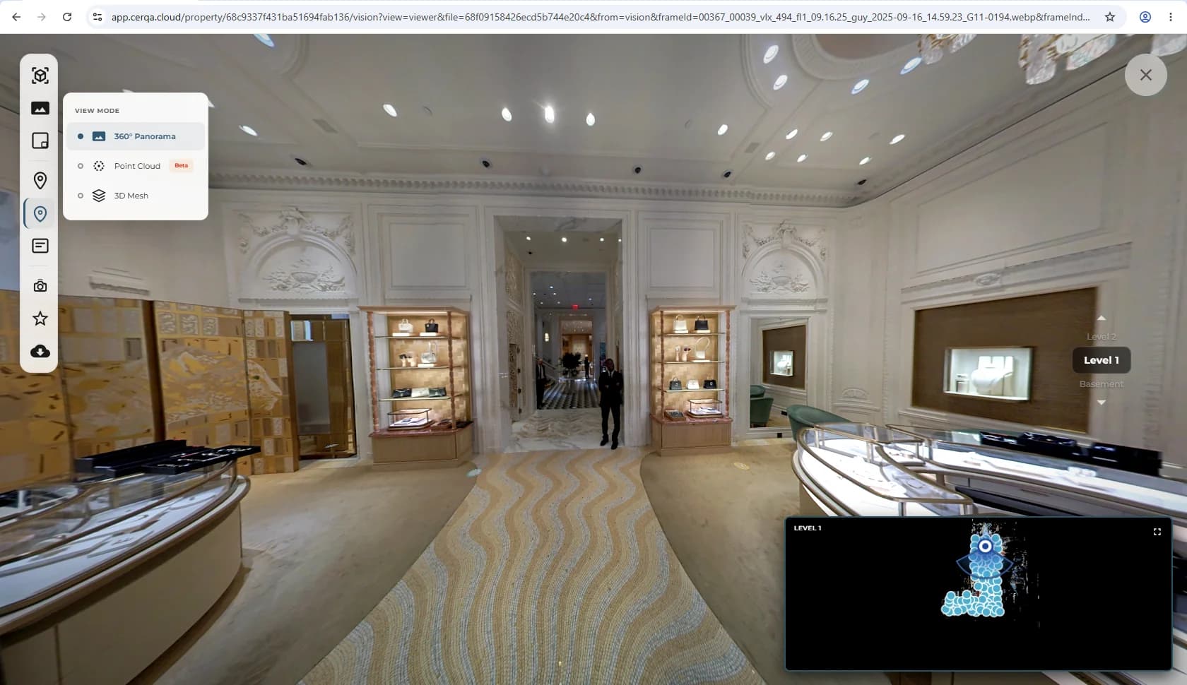
Point Cloud is Beta. 3D Mesh is NOT.
The Beta badge in the VIEW MODE control sits on Point Cloud, not on 3D Mesh. The mesh view is stable and backs the Vision mesh tooling. If you see “Beta” near 3D Mesh on your screen, look again - the badge is on the Point Cloud option directly above it.
Jumping to a 360 from a pin, and switching between levels
Whichever LAYOUT you pick, the floor plan stays interactive (in Floor Plan or Split View; in Immersive the mini-map in the bottom-right corner is also clickable). Click a pin to enter the 360 at that location. Pin semantics match VS-01: every pin marks a 360 capture location and is a navigation hotspot. From the floor plan, every pin is visible and clickable; from inside a 360, only spatially-near pins overlay in the panorama.
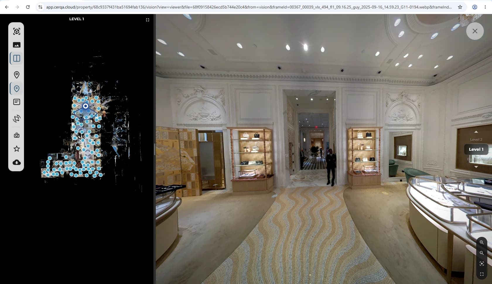
For multi-floor properties, the level selector on the right (e.g. Level 2 / Level 1 / Basement) switches between floors. Each level carries its own plan and its own pin set; switching levels clears the active 360 and shows the new plan, ready for another pin click.
Field pins are a different surface
Vision pins mark 360 capture locations and are the entry points into walkthroughs. The Field module's pins on a property mark issue or punch-list items and are filtered by date in the Field tab. Different modules, different pin semantics, different surfaces - for Field pins, see FL-01 - Field overview.
Related pieces
- VS-01 - Vision & 360 walkthroughs overview - walkthrough pins, entering a 360, Capture image, and the Viewpoints panel.
- VS-03 - Vision annotations & measurements - text annotations and the 4-mode Beta measurement suite, both available once you're inside a 360 regardless of LAYOUT or VIEW MODE.
- VS-05 - Vision mesh tools - the measurement tooling backed by the 3D Mesh VIEW MODE. Use 3D Mesh when measurement accuracy matters.
- FL-01 - Field overview - the Field module's desktop experience, including the 'Filter Pins by Date' control. Field pins are a different surface from Vision pins; this link is for the Field side.